






eBits Academy / ESP32 & LED
Your First Circuit: Make an LED Blink with ESP32
Make an LED blink with ESP32 and learn how the connections work.
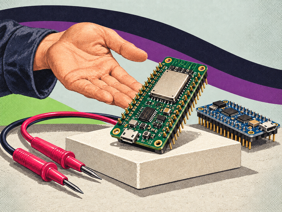
A small light is a good first project. It gives a visible answer to three questions: is the board running, is the circuit connected, and is the program doing what you expect? Start with one output before adding sensors, wireless connections, or batteries.
This example applies to the ESP32 DEV KIT DOIT with the original ESP32 chip and uses GPIO23. This is not a universal pin location for all boards in the ESP32 family. If you have another model, check its pinout and choose a suitable output before building. Espressif's GPIO reference lists GPIO23 as an input and output on the original ESP32.
Gather the few parts you need
- One ESP32 DEV KIT DOIT.
- A USB data cable that fits the board.
- A breadboard and jumper wires.
- One ordinary red indicator LED.
- One 330 Ω resistor in series with the LED.
Find the basic parts under components, tools and prototyping and connections. Check what is included with the board before ordering accessories.
Understand the connection before building
The current path should be:
GPIO23 → 330 Ω resistor → LED anode (+) → LED cathode (−) → GND
The resistor limits current. Do not connect the LED directly between the output and GND. On many through-hole LEDs, the long lead is the anode and the short lead is the cathode; a flat edge on the body often marks the cathode. If the leads have been cut or the type is different, consult the component documentation. Adafruit's LED introduction explains polarity and current limiting.
ESP32 uses 3.3 V logic on its GPIOs. Having USB or a 5 V power connection on the board does not mean the signal pins tolerate 5 V. Keep this first circuit to GPIO23 and GND, and leave external power supplies and batteries disconnected.
Build with the power disconnected
- Unplug USB before moving wires or components.
- Find the markings 23 and GND on the board. Use the markings, not a position remembered from another board.
- Connect GPIO23 to one end of the resistor. Connect the other end to the LED anode, then connect the cathode to GND.
- Check that the two LED leads are in different connected groups on the breadboard. Trace the entire circuit one connection at a time.
- Connect USB only after checking the connections.
Breadboard holes are connected in groups, and the power rails may be split in the middle. The center groove separates the two sides. Adafruit's breadboard guide shows the connections. If in doubt, use a continuity test with the power disconnected to identify connected holes.
Upload a simple program
Install the ESP32 board package following Espressif's Arduino guideand select the corresponding classic ESP32 board and its USB port. Use this short sketch:
#include <Arduino.h>
constexpr uint8_t statusLed = 23;

void setup() {
  pinMode(statusLed, OUTPUT);
}

void loop() {
  digitalWrite(statusLed, HIGH);
  delay(500);
  digitalWrite(statusLed, LOW);
  delay(500);
}
The output is high for half a second and low for half a second. The LED should repeat this pattern. pinMode selects the pin's function, and digitalWrite changes the output state. See the Arduino-ESP32 GPIO API.
If the light does not turn on
- No USB port: Try a known data cable, check the connector, and follow the board manufacturer's driver instructions.
- Upload fails: Check the board and port selection and follow the board's documented boot and upload procedure.
- The program uploaded, but the LED stays dark: Disconnect the power and check polarity, GPIO23, GND, and the breadboard's connected groups.
- Something gets hot: Disconnect USB and check for a short circuit before trying again.
Change one thing at a time. A clear photo, the exact board name, and the error message make it easier to help than “it doesn't work”.
Give your first success a new task
Change both pauses to 1,000 milliseconds and predict the result before uploading. Then try a short flash followed by a longer pause. You are practicing connecting a visible result to a precise instruction.
The next step could be Bluetooth connections or Meshtastic radio nodes. For help choosing, tell eBits about your project.
 Meshtastic
Get started with Meshtastic
From choosing a board and antenna to your first message between two radio nodes.
Read the guide Bluetooth
Understand Bluetooth
Classic, BLE and the choices that make your next wireless project easier.
Read the guide ESP32 & LED
Build your first circuit
Make an LED blink with ESP32 and understand the connections.
Read the guide